
OSI stands for Open Systems Interconnection , where open stands to say non-proprietary. It is a 7-layer architecture with each layer having specific functionality to perform. All these 7 layers work collaboratively to transmit the data from one person to another across the globe. The OSI reference model was developed by ISO – ‘International Organization for Standardization ‘, in the year 1984.
The OSI model provides a theoretical foundation for understanding network communication . However, it is usually not directly implemented in its entirety in real-world networking hardware or software . Instead, specific protocols and technologies are often designed based on the principles outlined in the OSI model to facilitate efficient data transmission and networking operations
The OSI model, created in 1984 by ISO , is a reference framework that explains the process of transmitting data between computers. It is divided into seven layers that work together to carry out specialised network functions , allowing for a more systematic approach to networking.
For those preparing for competitive exams like GATE, a strong understanding of networking concepts, including the OSI model, is crucial. To deepen your knowledge in this area and other key computer science topics, consider enrolling in the GATE CS Self-Paced course . This course offers comprehensive coverage of the syllabus, helping you build a solid foundation for your exam preparation.
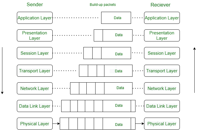
When we transfer information from one device to another, it travels through 7 layers of OSI model. First data travels down through 7 layers from the sender’s end and then climbs back 7 layers on the receiver’s end.
Data flows through the OSI model in a step-by-step process:
Each layer adds specific information to ensure the data reaches its destination correctly, and these steps are reversed upon arrival.
Let’s look at it with an Example:
Luffy sends an e-mail to his friend Zoro.
Step 1: Luffy interacts with e-mail application like Gmail , outlook , etc. Writes his email to send. (This happens in Layer 7: Application layer )
Step 2: Mail application prepares for data transmission like encrypting data and formatting it for transmission. (This happens in Layer 6: Presentation Layer )
Step 3: There is a connection established between the sender and receiver on the internet. (This happens in Layer 5: Session Layer )
Step 4: Email data is broken into smaller segments. It adds sequence number and error-checking information to maintain the reliability of the information. (This happens in Layer 4: Transport Layer )
Step 5: Addressing of packets is done in order to find the best route for transfer. (This happens in Layer 3: Network Layer )
Step 6: Data packets are encapsulated into frames, then MAC address is added for local devices and then it checks for error using error detection. (This happens in Layer 2: Data Link Layer )
Step 7: Lastly Frames are transmitted in the form of electrical/ optical signals over a physical network medium like ethernet cable or WiFi.
After the email reaches the receiver i.e. Zoro, the process will reverse and decrypt the e-mail content. At last, the email will be shown on Zoro’s email client.
The OSI model consists of seven abstraction layers arranged in a top-down order:
The lowest layer of the OSI reference model is the physical layer. It is responsible for the actual physical connection between the devices. The physical layer contains information in the form of bits. It is responsible for transmitting individual bits from one node to the next. When receiving data, this layer will get the signal received and convert it into 0s and 1s and send them to the Data Link layer, which will put the frame back together.

The data link layer is responsible for the node-to-node delivery of the message. The main function of this layer is to make sure data transfer is error-free from one node to another, over the physical layer. When a packet arrives in a network, it is the responsibility of the DLL to transmit it to the Host using its MAC address .
The Data Link Layer is divided into two sublayers:
The packet received from the Network layer is further divided into frames depending on the frame size of the NIC(Network Interface Card). DLL also encapsulates Sender and Receiver’s MAC address in the header.
The Receiver’s MAC address is obtained by placing an ARP(Address Resolution Protocol) request onto the wire asking “Who has that IP address?” and the destination host will reply with its MAC address.

The network layer works for the transmission of data from one host to the other located in different networks. It also takes care of packet routing i.e. selection of the shortest path to transmit the packet, from the number of routes available. The sender & receiver’s IP address es are placed in the header by the network layer.
The transport layer provides services to the application layer and takes services from the network layer. The data in the transport layer is referred to as Segments . It is responsible for the end-to-end delivery of the complete message. The transport layer also provides the acknowledgment of the successful data transmission and re-transmits the data if an error is found.
At the sender’s side: The transport layer receives the formatted data from the upper layers, performs Segmentation , and also implements Flow and error control to ensure proper data transmission. It also adds Source and Destination port number s in its header and forwards the segmented data to the Network Layer.
Note: The sender needs to know the port number associated with the receiver’s application.
Generally, this destination port number is configured, either by default or manually. For example, when a web application requests a web server, it typically uses port number 80, because this is the default port assigned to web applications. Many applications have default ports assigned.
At the receiver’s side: Transport Layer reads the port number from its header and forwards the Data which it has received to the respective application. It also performs sequencing and reassembling of the segmented data.
1. Connection-Oriented Service: It is a three-phase process that includes:
In this type of transmission, the receiving device sends an acknowledgment, back to the source after a packet or group of packets is received. This type of transmission is reliable and secure.
2. Connectionless service: It is a one-phase process and includes Data Transfer. In this type of transmission, the receiver does not acknowledge receipt of a packet. This approach allows for much faster communication between devices. Connection-oriented service is more reliable than connectionless Service.
This layer is responsible for the establishment of connection, maintenance of sessions, and authentication, and also ensures security.
Example
Let us consider a scenario where a user wants to send a message through some Messenger application running in their browser. The “ Messenger ” here acts as the application layer which provides the user with an interface to create the data. This message or so-called Data is compressed, optionally encrypted (if the data is sensitive), and converted into bits (0’s and 1’s) so that it can be transmitted.

Communication in Session Layer
The presentation layer is also called the Translation layer . The data from the application layer is extracted here and manipulated as per the required format to transmit over the network.
Note: Device or Protocol Use: JPEG, MPEG, GIF.
At the very top of the OSI Reference Model stack of layers, we find the Application layer which is implemented by the network applications. These applications produce the data to be transferred over the network. This layer also serves as a window for the application services to access the network and for displaying the received information to the user.
Example : Application – Browsers, Skype Messenger, etc.
Note: The application Layer is also called Desktop Layer.
Device or Protocol Use : SMTP .
The main functions of the application layer are given below.
Note: The OSI model acts as a reference model and is not implemented on the Internet because of its late invention. The current model being used is the TCP/IP model.
Layer No
Layer Name
Responsibility
Information Form (Data Unit)
Device or Protocol
TCP/IP protocol ( Transfer Control Protocol/Internet Protocol ) was created by U.S. Department of Defense’s Advanced Research Projects Agency (ARPA) in 1970s.
Some key differences between the OSI model and the TCP/IP Model are:

Even though the modern Internet doesn’t strictly use the OSI Model (it uses a simpler Internet protocol suite), the OSI Model is still very helpful for solving network problems. Whether it’s one person having trouble getting their laptop online, or a website being down for thousands of users, the OSI Model helps to identify the problem. If you can narrow down the issue to one specific layer of the model, you can avoid a lot of unnecessary work.
Imperva security solutions protect your applications at different levels of the OSI model. They use DDoS mitigation to secure the network layer and provide web application firewall (WAF), bot management, and API security to protect the application layer.
To secure applications and networks across the OSI stack, Imperva offers multi-layered protection to ensure websites and applications are always available, accessible, and safe. The Imperva application security solution includes:
The OSI Model defines the communication of a computing system into 7 different layers. Its advantages include:
In conclusion, the OSI (Open Systems Interconnection) model is a conceptual framework that standardizes the functions of a telecommunication or computing system into seven distinct layers: Physical, Data Link, Network, Transport, Session, Presentation, and Application. Each layer has specific responsibilities and interacts with the layers directly above and below it, ensuring seamless communication and data exchange across diverse network environments. Understanding the OSI model helps in troubleshooting network issues, designing robust network architectures, and facilitating interoperability between different networking products and technologies.
Yes, the OSI model is still used by networking professionals to understand data abstraction paths and processes better.
Layer 7 or Application layer is highest layer of OSI model.
Layer 8 doesn’t actually exist in the OSI model but is often jokingly used to refer to the end user. For example: a layer 8 error would be a user error.